2023
09.07
Students in my space hardware class again wrote the STK Certification test this year. My own certification had expired awhile ago so I decided to write it myself. A little bit of pressure on me because if I had not passed and anyone in the classed had…
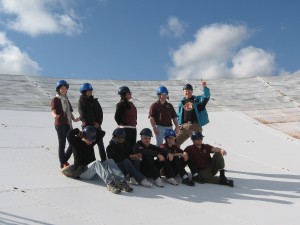
Anyway it all worked out for the best – when we were on our annual “dish walk” at ARO, three of us who passed the test posed in an “AGI inspired” formation. I sent the picture to AGI and they posted it on their Facebook page. The picture I sent is below…
2017
11.06
Two years ago I received a Category II AIF (Academic Innovation Fund) award from the AVP Teaching & Learning at York University to develop a vibration test experiment for the Space Engineering curriculum. All spacecraft and components undergo a number of environmental tests to ensure they will function correctly after launch and during exposure to on-orbit conditions. The goal of the experiment for our students was to give them an exposure to a typical vibration test for a spacecraft or spacecraft component. (I have also received a second AIF award for a Thermal-Vacuum test – more on that in a later post).
With the AIF funding, I decided to design and build a Printed-Circuit Board which would have a number of chip accelerometers (ADXL345). This would allow students to perform the usual vibration test, where acceleration on the board is measured by test accelerometers, but also in later experiments monitor acceleration from up to 7 different locations on the board. With a larger number of monitored locations, it allows the students to possibly study vibration mode shapes (the devices themselves provide a max bandwidth of 1.6 kHz – max sample rate of 3.2 kHz). It actually turns out that the measurement acquisition problem is more challenging than the vibration problem. So this allows the hardware to be re-used in a second experiment in another course that I teach in the Space Engineering curriculum.
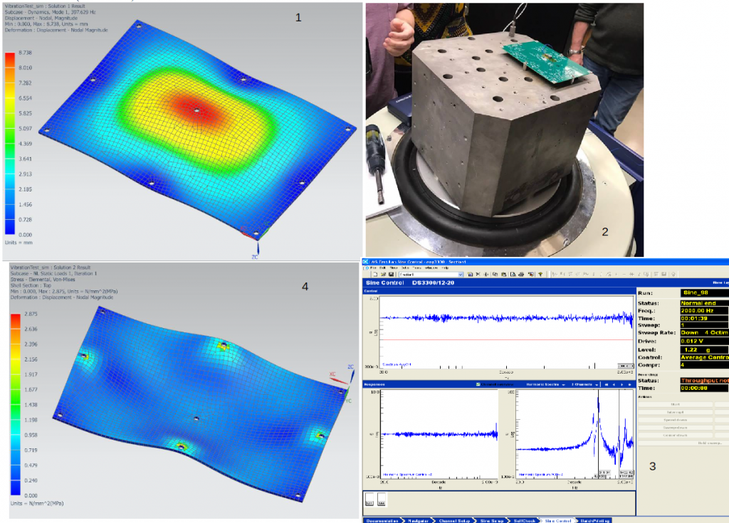
I have been running the vibration experiment for 2 offerings of ENG 3330 (Materials for Space Application) – the students perform finite element analysis and calculate the board Normal modes and response to sine and random inputs. We are using Prof. Ben Quine’s shaker facility to do this (thanks to Ben for allowing us to do this every year). It’s a 4-step process as shown in the Figure below:
1. Students predict the Normal modes of the PCB prior to the test. Here we use NX and NX Nastran (space industry standard software tools).
2. We run the test using the shaker facility – Low level sine, Full level sine and random vibration tests. Test levels are based on the Nanoracks tests specified for CubeSats released from the ISS.
3. The students take the measured outputs from the shaker and compare them with the predicted results. (Reflection component of experiential learning)
4. The final step is to perform a stress prediction for the Full level sine and random vibration tests to show the structure’s margin of safety and hence providing evidence of its ability to survive launch and work in space (i.e. its now “qualified” for launch).
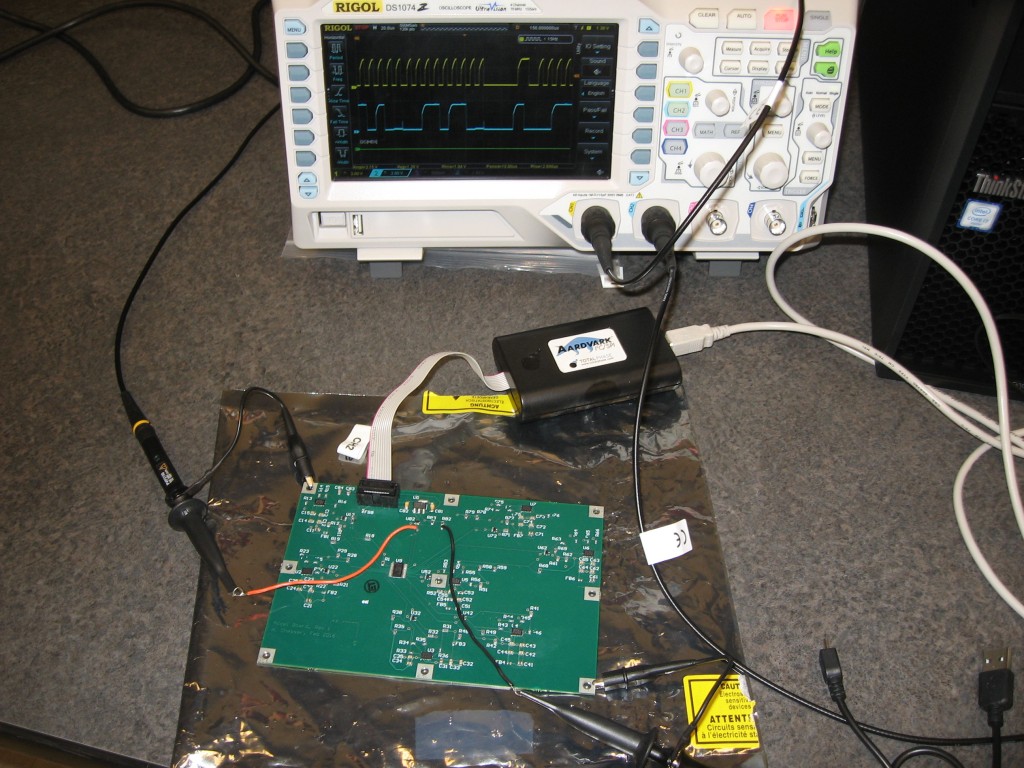
This year I have re-used the same PCB in a second experiment this time for ENG 4350 (Space Hardware) to get the students learning about I2C communications and data acquisition with LabVIEW. The accelerometers are read using an Aardvark I2C adapter which plugs into a USB port of a Windows PC. Not the best platform for high speed data acquisition, but it is the standard lab set-up we have. We break out the I2C lines to the board so that students can use a scope to look at the I2C messages and use the scope’s decoding functions. The experiment has students talking to both a multiplexer and the 7 accelerometer chips on the board. This second experiment is shown in the figure below:
2012
05.30
Analytical Graphics (AGI) were so happy that a bunch of my students in ENG/PHYS 4350 became “STK Certified Rocket Scientists” that they blogged about it here (post has been taken down from AGIs site). We use STK in the course to help the students develop code which tracks GPS satellites – see my previous blog posts on how this is done.
This year I “encouraged” (i.e. gave a bit of course credit) to students who took and passed AGI’s STK Certification Exam. When we went on our annual field trip to the Algonquin Radio Observatory (ARO) I thought it would be fun if we all posed in the shirts that AGI sends to anyone who passes the exam. I sent the photo to AGI and they wanted to post it on their blog. Another photo that was taken on our “dish walk” during the field trip is given below showing the class and Nick Balaskas who helps out with the field trip every year. Not shown is Sasha Novikov the course technician and Ben Quine from Thoth Technologies who operate the facility.
2012
04.01
This year the ENG 1000 class demonstrated their designs during York’s Spring Gala event. We held it in a great location – Lassonde Building Lecture Hall A. Each year I am amazed at how the students respond to this activity - whether its because of the creative nature of design challenges, the lure of the subject of robotics or the thrill of competition. I show here a selection of the design concepts created by the students using the Vex robotics kit that we issue each of the teams.
We have 2 events as part of the competition, the first is a radio control event and the second is an autonomous event.
2011
05.05
Last week I took my ENG/PHYS 4350 class to ARO for the annual GPS satellite tracking exercise. For the past few years we have been doing a reduced set of tests, but this year, thanks to the efforts of Thoth Technologies and faculty colleague Ben Quine, the station is now fully functional. All student groups showed that they had “the right stuff” as their code was able to predict where selected GPS satellites would be – so they were able to “track” the satellite.
Their code produces a command file which tells the antenna control system azimuth and elevation
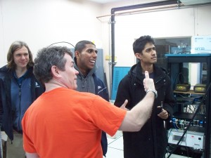
"Thumb's Up" Tracking Conditions Achieved
positions. We give the command file to the pointing computer and then hook up a spectrum analyzer to see the GPS L-band transmission. If the angles are correct (to within about 40 arcminutes, which is the 3 dB beamwidth of the antenna), then we see the L-band spectrum (the “Thumbs Up” condition).
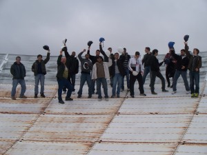
York Space Engineers: Dishing it out...
One of the highlights of the visit is a “dish walk” on the 46-m reflector surface – the class and I posed for a picture. Not sure how many more years we will be doing this because the surface is being painted. Many thanks to Nick Balaskas (and Ben) for taking some excellent “action” shots of the event.
ENG/PHYS 4350 Space Hardware is a 4th year course offered to space engineering, space science and physics students (it is compulsory for space engineers). For more details see my Teaching page.
2011
04.18
My ENG 1000 class was invited back to the Ontario Science Centre to hold the annual Murphy’s Cup. 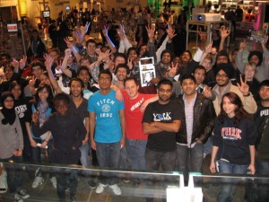 I snapped this picture of the assembled class after the competition that was held April 2nd. Many thanks to the Science Centre for providing a superb venue for the competition. The students really enjoyed the day. Watch this post for updates as we put together some of the video footage that was shot during the competition.
ENG 1000 is a first year course – I teach the winter semester portion and as part of it we have a robot design competition. For more details see my Teaching page.


