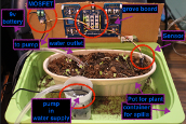
The Arduino-compatible Grove board that we use in EECS 1021 and EECS 1011 at York University has multiple analogue sensors on it. Other analogue sensors, like the soil moisture sensor, can be attached to the board using either the Arduino headers (in yellow) or with the Grove connectors.
Students in EECS 1011 and 1021 are to obtain a multimeter, either through the Bookstore or other means, to verify voltages from these sensors. There are a few different ways that you can do that.
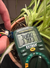
Note that, typically, the sensors are running with outputs between 0 volts and 5 volts. Some, however, will run between 0v and about 3v. Yes, there are other voltage ranges possible, but they're not as common. But, always check the documentation for the part you're using. Regardless, you should normally set your multimeter to measure in DC voltage and with a 5 volt range, as that's the most common setting for this context.
Next, you will need to connect the probes of your multimeter to the sensor. There are a few ways to do that.
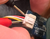
Option 1: measure at the crimps, internally.
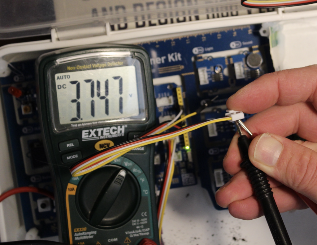
One way is to "jam" the probe ends into the sensor connector and to have them touch the metal crimps on the inside. The following photo shows this:
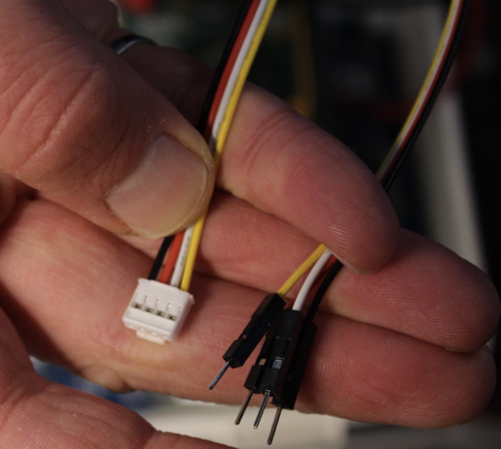
Option 2: measure at the crimps, externally.
Here, use one of the extra cables in your lab kit. One end has "breadboard" style pins and the other has a Grove connector. Black is to connect to Ground, Red to 5v, and the White and Yellow are meant to be signals. Look at the labels on the yellow headers on your board. Connect the Black to ground on your Grove board, Red to 5V and the white and yellow lines to the signal (like A1) that you are interested in.
Look at the Grove connector. There are four little metal squares exposed. You can measure there. Each little metal square corresponds to one of the wires (the one directly above it). Your multimeter probes can touch there.
Now you can measure one of the signal wires as long as the other multimeter lead is touching Ground, as you can see here:
Option 3: Attach solid core wires to the Arduino headers
The third option requires you to have solid core wires and/or a breadboard. Plug those into the Arduino headers and measure. These wires are not in your kit.
James Andrew Smith is a Professional Engineer and Associate Professor in the Electrical Engineering and Computer Science Department of York University’s Lassonde School, with degrees in Electrical and Mechanical Engineering from the University of Alberta and McGill University. Previously a program director in biomedical engineering, his research background spans robotics, locomotion, human birth, music and engineering education. While on sabbatical in 2018-19 with his wife and kids he lived in Strasbourg, France and he taught at the INSA Strasbourg and Hochschule Karlsruhe and wrote about his personal and professional perspectives. James is a proponent of using social media to advocate for justice, equity, diversity and inclusion as well as evidence-based applications of research in the public sphere. You can find him on Twitter. You can find him on BlueSky. Originally from Québec City, he now lives in Toronto, Canada.